“Make it work, make it happen, and make it right. Once you create something, your name is on it"
TORSION RIG

In order to be able to find structural flaw in a rigid body structure such as a chassis, one must perform a series of quantitative tests, collect high-precision data, and perform data analysis. For the Illini Formula Electric team, I was tasked with finding a way to make the rigidity of the chassis stiffer, but also make it lighter. One way to improve the 'stiffness' of the chassis was to look at its torsion rigidity and locate certain points/tubes that were not handling the stresses.
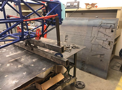
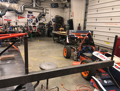
The images above and below show a simple and powerful torsion rigidity test equipment that I designed for that year's chassis model. The goal was to measure torsional stress acting at various points on the chassis used for a previous competition and determine structural flaws to remove in new chassis model.
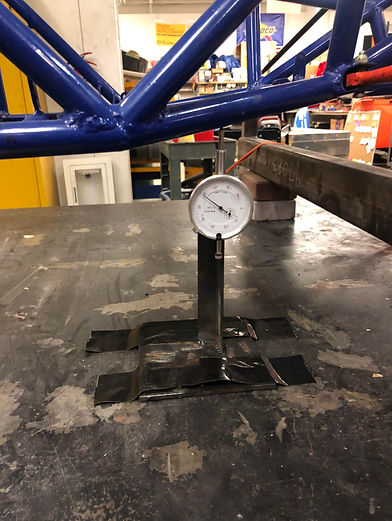
The testing equipment allows the chassis to be constrained from one side (the backside in this case) while applying a moment on the other side of the chassis (the frontside in this case). Therefore, applying a torsional stress on the chassis. Also, the chassis lies on a small pivot as in the image to the bottom right.


The images below show the testing equipment setup after I, with the help of a few teammates, fabricated it using scrap pieces of square tubes and plates. We used cut saw, grinders, and welding equipment to put it together.
After that, we performed 4 repetitive tests to collect a large amount of data (to minimize range errors in the data) using a pressure/stress gauge. Using Excel and cross-referencing the data trends with Finite Element Analysis simulations, my co-lead and I were able to determine flaws in the chassis that helped reduce unnecessary weight and improved the rigidity of the chassis.